
Product Knowledge
What is High-speed Cable Processing Equipment and How to Use It Effectively?
What high-speed cable processing equipment means in this guide
This guide covers equipment used to prepare high-speed data-cable cores for later soldering or assembly. High-speed describes the cable application, rather than a guaranteed processing rate. The equipment scope depends on the cable structure and the operation required at its termination.
Cable preparation is one part of manufacturing a cable assembly. It should be distinguished from upstream conductor drawing, insulation extrusion, and cable manufacture, as well as from later assembly and finished-product testing. A machine that performs one of these stages does not automatically provide the others.
Match the preparation equipment to the actual workpiece
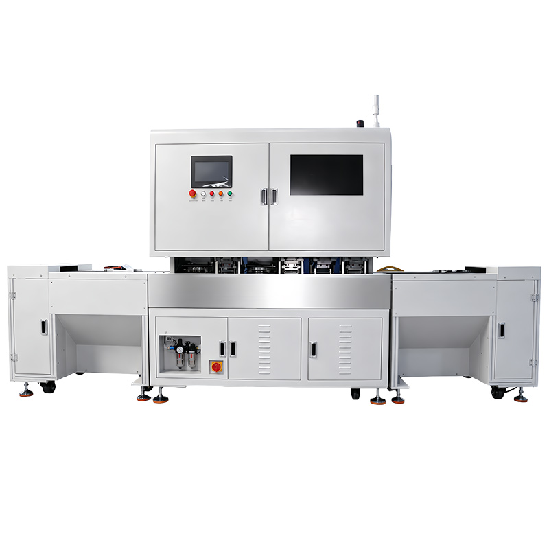
MIJOINT's documented equipment includes a semi-automatic cable preparing machine, a CDFP cable preparing line, and an external high-speed cable QSFP-DD preparing line. Their names identify equipment options, not a single interchangeable configuration for every cable.
The semi-automatic cable preparing machine uses manual wire-clamp loading and fixture-based transfer. The CDFP preparation-line description also identifies a manual loading table. Review these handling tasks when planning staffing and equipment interfaces.
For each option, compare the cable construction, loading condition, fixture, required preparation stages, and intended output. A model designation alone does not establish compatibility with every cable or connector sold under that designation.
Specify what must enter and leave each preparation stage
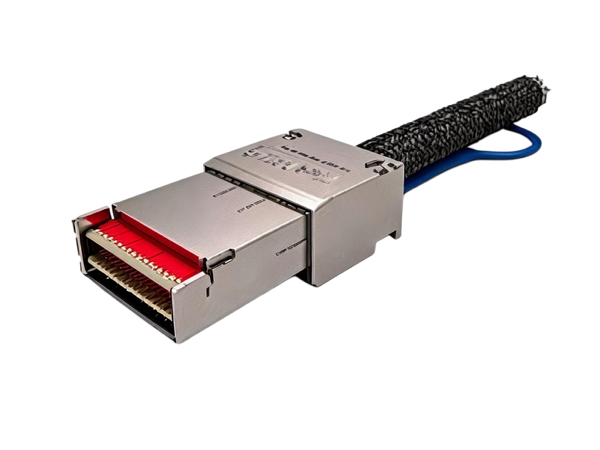
Start with a cable cross-section and the termination drawing. Identify the layers to retain, the areas to expose, and the required conductor positions at the next operation. Record dimensional tolerances and the condition of incoming cut lengths, cores, and fixtures.
For a proposed preparation stage, agree its input, output, and defect criteria. Material removal, conductor forming, and end trimming are separate requirements; their inclusion and sequence must follow the actual equipment configuration. This process definition is more useful than assuming that every cable processing machine performs a standard cut-strip-crimp sequence.
Use an approved setup and confirm the first piece
Set up the equipment using its operating instructions, the correct fixture, and the approved parameters for the product. Confirm the incoming material and drawing revision before checking the first prepared sample against the agreed dimensions and condition.
Changes to cable structure, materials, tooling, or the next assembly stage should trigger a review of the approved setup. Record the change and its validation outcome. Do not transfer stripping or heating settings from another machine or material simply because the product names are similar.
Operator checks, maintenance, and fault recovery remain part of production planning. Define these tasks for the selected machine instead of treating automation as a guarantee that variation or handling errors disappear.
Keep preparation checks separate from finished-assembly validation
Prepared-core inspection can address the dimensions and condition defined for that stage. Later soldering, connector assembly, and finished-cable performance require their own acceptance criteria. Do not treat a satisfactory prepared sample as proof that all later requirements have been met.
Agree which checks occur in the machine, at a separate station, or during sample validation. Clarify any required record fields and how they connect to the product or batch. A request for inspection or traceability should become a documented project requirement rather than an assumed standard feature.
Find the relevant equipment and define the next operation
Review the semi-automatic cable preparing machine for its documented core-preparation scope. For model-specific requirements, see the CDFP cable preparing line or the QSFP-DD cable preparing line. Compare their actual processing and handling boundaries before selecting a configuration.
For a project covering later assembly as well, use the cable assembly line selection guide to define the wider equipment boundary. Send the cable structure, drawings or samples, and required output condition to discuss a custom preparation solution.